Mechatronics Fundamentals - Electronics
The electronics basics behind an algae device: microcontrollers, circuits, and components
In previous updates, I talked about optimizing the cost of algae and different products you can make. In this update (and future ones) I will be introducing the different aspects of mechatronics, and the disciplined needed to build the algae hardware device. In this update, I will be introducing electronics which includes anything from components of a microcontroller, to building circuitry and many more.
What is Mechatronics?
Mechatronics is a discipline that integrates electrical, mechanical, and software components together to build hardware. A mechatronic device has 3 core components: sensors, microcontrollers, and actuators. Sensors tell you what is happening (ex. telling you the temperature in °C). Microcontrollers take information from the sensor and then decide on the best action for the actuator. Microcontrollers make the decision based on the software program that is written on them. Actuators are the devices that do the action in the software program.
Example Application for Algae
Here is an example that is useful for algae. The optimal temperature is around 25 °C. The sensor detects the temperature at 20°C. The microcontroller program has instructions to deal with this. If the sensor temperature is below 25°C increase the heat input, if the temperature sensor is above then reduce the heat input. In this case, the temperature is below 25°C so we will activate our actuator to increase the temperature in the tank to reach optimal temperature.
Microcontrollers (MCUs)
The microcontroller is an integrated circuit that is used for controller operations of our mechatronic device.
Elements of a Microcontroller
Microcontrollers have 3 main components. Memory, central processing unit (CPU), and input/output devices. All of them are connected by a data bus (a method of distributing and managing data in real time).
CPU — (Executes program instructions)
There are 3 main elements:
-
Control unit — generates timing signals and gets program instructions from memory to execute.
-
Arithmetic and Logic units — perform actual instruction on data
-
Registers: Memory holding locations while arithmetic and logic units are performing instruction.
Memory
Memory has 2 different types:
-
Volatile — your memory disappears if power is off
-
Non-volatile — your memory stays even if power is off
Microcontroller Basics
Breakout Board
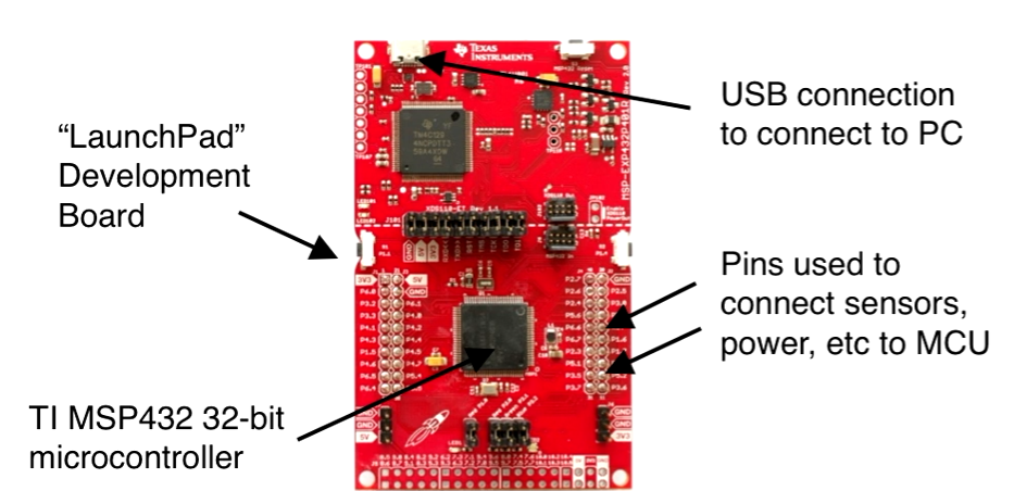
To be able to use an MCU we need to pair it with a breakout board (together called a development kit). You want a breakout board because it makes it easier to connect wires to an MCU. The image below shows the relative size difference between microcontrollers and breakout boards.
General Purpose Input-Output (GIPO) Pins
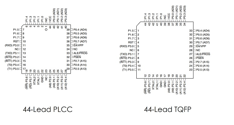
They allow the interface of your microcontroller with other devices like sensors and actuators. Shields are available for the MCU development kit for integrations between the development kit and other peripherals (sensors or motors). Shields can be placed directly on top of a microcontroller helping connect sensors or motors (an actuator) to MCU without wires.
The image below has an image of different pins in a microcontroller. The functionality of all of the pins can be found in the documentation of the microcontroller.
States of a Microcontroller
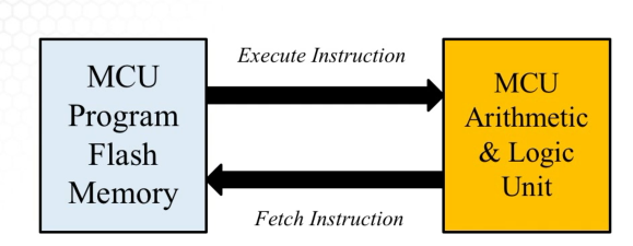
Programming Mode — External programmer (your development kit) writes a program towards flash memory. Your arithmetic & logic (A&L) unit is not doing much here.
Normal Operation Mode — You power your MCU and the flash memory executes instructions on the arithmetic & logic unit. The A&L unit fetches the next instruction from the flash memory. The cycle repeats.
You can execute code directly from your computer into the microcontroller. On your development kit, you have an onboard emulator which includes a USB connection to a PC. This helps program MCUs, enables debugging from a PC, and provides power to MCU from USB.
Electronic Circuits Components
Electronic Circuits carry electrical signals which carry information between MCUs, sensors, and actuators. Below are the different components, their symbol, unit of measurement, and circuit symbol.
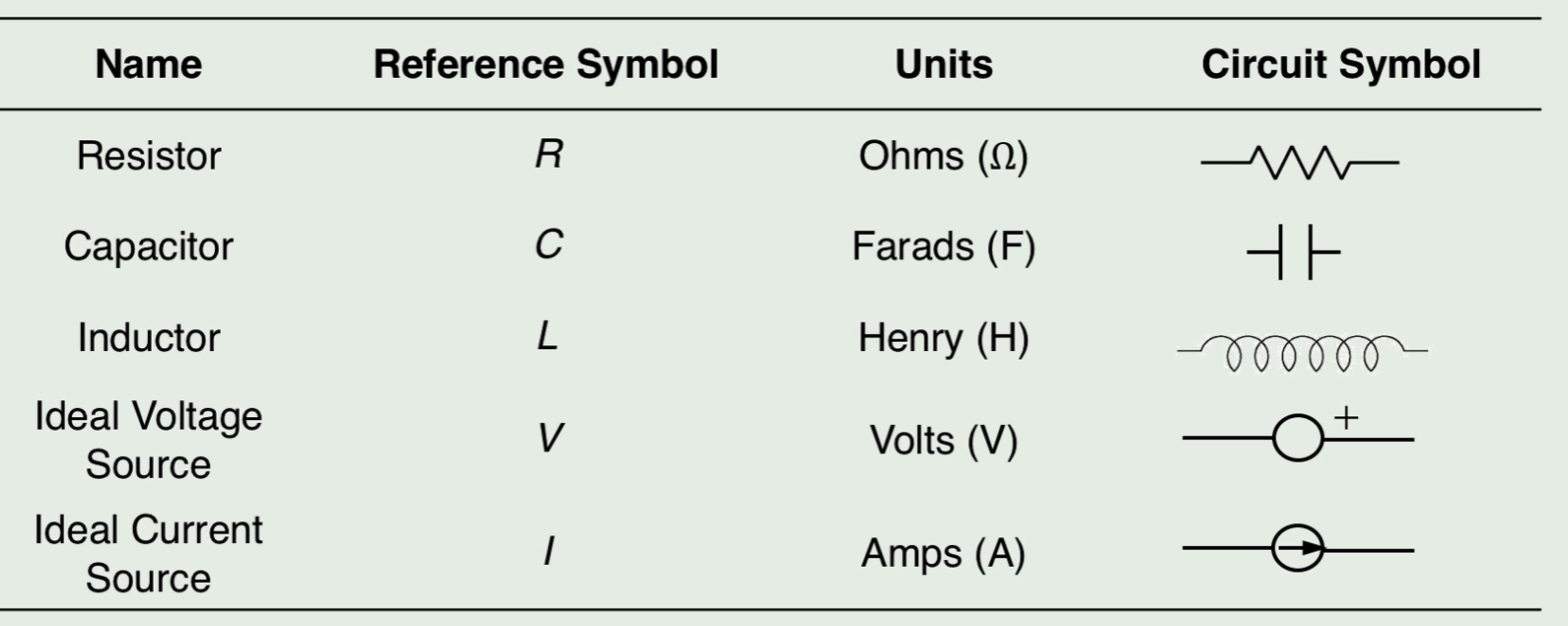
Resistor — a device that provides resistance to the passage of an electric current. This happens through the dissipating of some electrical energy into heat energy. This protects your components from a higher voltage (electrical energy) than they can handle.
Capacitor — a device that stores electrical energy. Similar to a resistor, but a different method of reducing energy input.
Inductor — a device that stores electrical energy in the form of magnetic energy.
Ideal voltage source — Voltage is the difference in electric potential between two points. Electric potential is the amount of work needed to move a unit charge. An ideal voltage source can maintain the fixed voltage independent of the load resistance or the output current. However, a real-world voltage source cannot supply unlimited current.
Ideal current source — Current is the rate of flow of electric charge. Similar to an ideal voltage source, but for current. Voltage is the cause of current (being an effect).
Important Relationships Governing How Voltage and Current Interact with Circuit Elements
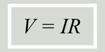
Relationship 1: Voltage and Current (Ohm’s Law) — Voltage = Current * resistance.
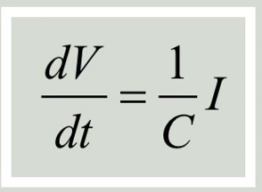
Relationship 2: Voltage, current, and capacitance — derivative of voltage = 1/capacitance * Current.
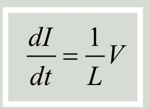
Relationship 3: Inductance and voltage — a derivative of current is 1/Inductance * Voltage.
The value of these relationships is to help us decide on the specification of our circuit elements. For example, based on the understanding of voltage and current we can decide how many Ohms of resistance we need for each resistor in the circuit.
Alternating Current Voltage vs DC Voltage
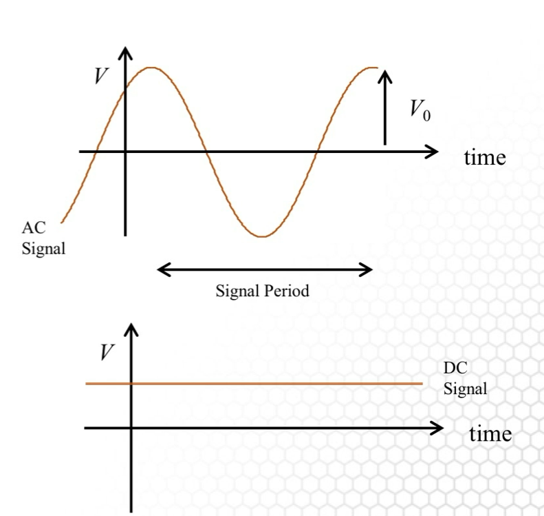
Alternating current (AC) voltage is sinusoidally varying voltage. When working with AC signals we need to generalize resistance (since it is not constant), this is called impedance. Direct current (DC) voltage is constant voltage over time. The difference is AC changes direction periodically (relevant to the sinusoidal pattern) and DC voltage only allows current to flow in 1 direction. Depending on the application you would use a different type of current. Below is an image showing the waveforms of both AC and DC voltages
Resistors and Power
Resistors provide resistance to the passage of an electric current, dissipating the electrical energy into heat energy. This protects your components from a higher voltage (electrical energy) than they can handle. To be able to finetune the resistance of a resistor we should use potentiometers.
They are variable resistors that can be tuned to precise values, which provides a better capacity for the user to adjust the resistance to a precise level (since normal resistors have discrete values).
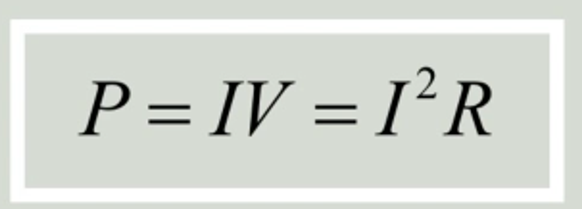
As you increase resistance, you increase your power dissipation you need to be aware of the amount of heat in the system. Below are the equations for both AC and DC voltage.
DC Power (or heat) dissipated = Current * voltage = current^2 * resistance
For AC voltage, you have time as an additional variable due to its sinusoidal nature. You can get instantaneous and average power for it. Equations below.
The AC voltage equations are similar to the DC ones. The difference is you have a new input of time with sine and cosine (based on the sinusoidal structure of AC voltage).

Power dissipation is an important specification for circuit elements. If your circuit power dissipation was higher than one of the circuit components, your device will overheat and fail.
Identifying Power Dissipation in Circuit Example
The circuit below has a 12V DC voltage and a resistance of 500 Ω, what is the minimum power rating you need for the resistor?
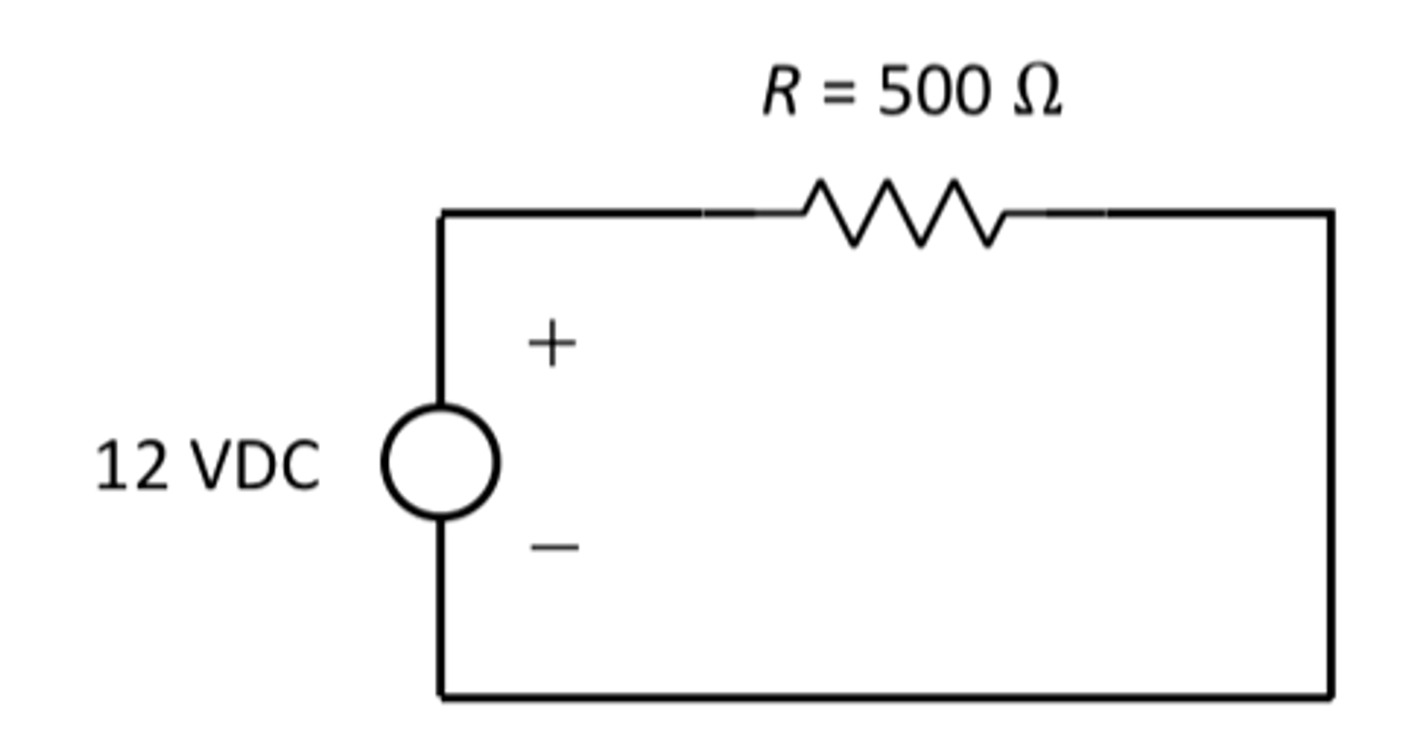
If we were to look at our DC voltage power dissipation formula we can see we don’t have the value for current. This means we need to start with our first Constitutive relationship — Ohms law
V=IR
V/R = I
12V/500Ω = 0.024A
P = IV
P = 0.024A * 12V
P= 0.29W
When buying the resistor you need to have a power rating of 0.29W or over. Otherwise, it can overheat and fail.
Kirchoff’s Current Law
The law is the sum of current into (or out of) a node is zero. A node is a location where I1 splits into I2 and I2. Kirchoff’s laws follow the same idea as the conservation of energy.
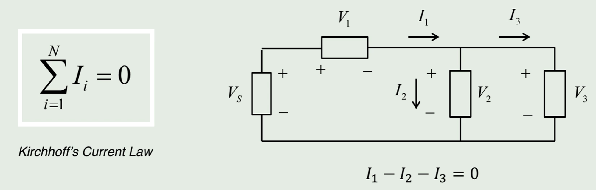
Summation notation on the left, circuit on the right.
When doing circuit analysis to find current we would be using Ohms law $V=IR$. We would then turn it into $I = V/R$
Kirchoff’s Voltage Law
Kirchoff’s voltage law is used for circuit analysis and understanding voltage regulator types.
The law is the sum of voltage drops and rises around any closes path in a circuit is 0.
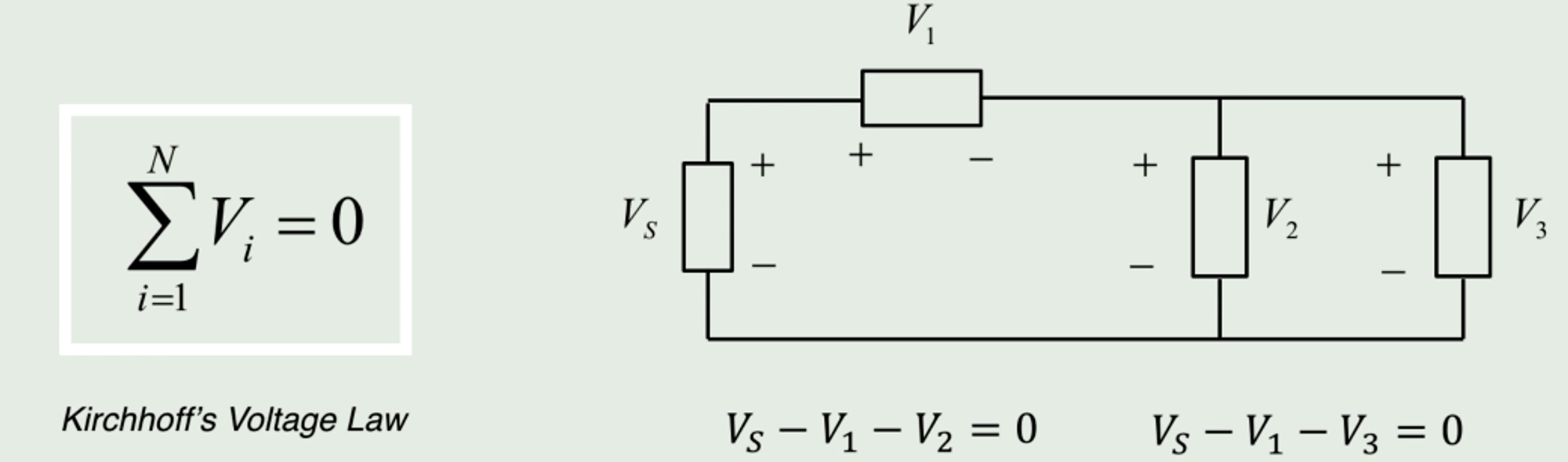
When doing circuit analysis to find current we would be using Ohms law V=IR. We would then turn it into I = V/R.
Reducing Voltage In a Circuit
Method 1: Voltage Divider
Sometimes you need to step down voltage otherwise your electrical components could overheat. This can be done using voltage dividers, created by placing resistors in series. They are used for sensor interfacing or reading potentiometer values (low current applications).
You use high values for your resistors (1k ohms - 10k ohms range). When stepping down a voltage you have your combined voltage drop Vi and to measure the voltage drop across resistor R2 that would be called V2 related by the following equation.
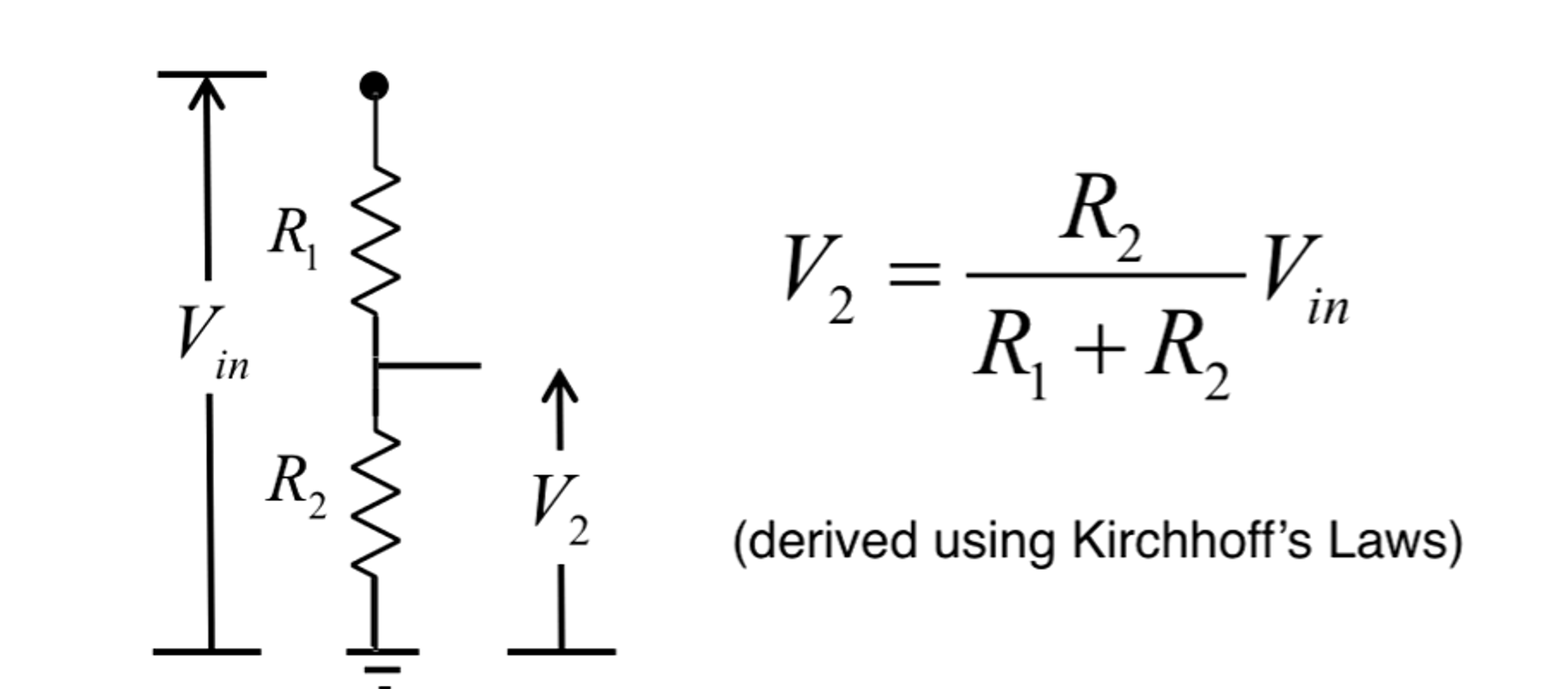
The left side is the circuit where we are measuring the voltage drop across resistor 2 and the right shows the equation to find V2.
Using Voltage Divider Example
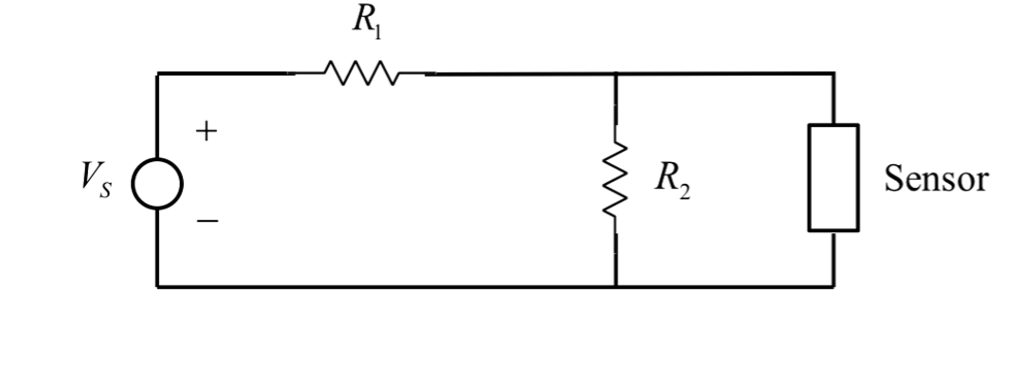
You have a sensor that requires an input of 5V DC. You have a voltage source that provides 15VDC. Design a voltage divider (find R1 and R2) that will allow you to power the sensor from this power supply. In this case, we will make the arbitrary decision to have the R1 resistor be 1k Ω.
V_2 = (R_2/R_1 + R_2) * V_i
V_2/V_i = (R_2/R_1 + R_2)
5/15 = (R_2/1000 + R_2)
R_2 = 500 Ω
Typically 500-ohm resistors are not available. We would need tight tolerances, for that we can use a potentiometer. Also, know that if you have 5.1V or 4.9V for your sensor it should still work.
Method 2: Voltage regulator
Voltage regulators are used to stepping down voltages for motors and LEDs (high current applications). Voltage regulators provide a single output voltage (e.g. 5V) for a range of input voltages (7-35V). This is helpful when you have voltages that change. If one day you had 10V and the next it spiked to 10.5V you would still have the same output of 5V.
Types of voltage regulators
-
Linear voltage regulators use an operational amplifier (op-amp) and transistor to achieve stable output voltage. They have a dropout voltage value of about 2V. If we wanted to have a 5V input then we would need 7V or higher to account for the dropout voltage.
-
Switching Regulators — the path is switched on and off (toggle switches) quickly to reduce average voltage. These devices have a 95% efficiency vs a 60-70% efficiency with linear regulators. The benefit is you need less power and you have less power dissipation than linear. The trade-off is switching regulators are more complex.
Operational Amplifier
Many sensors have an output voltage signal that is too small to be read by a microcontroller. To amplify the signal you will an operational-amplifier (op-amp) circuit.
Type 1: Open-loop operation
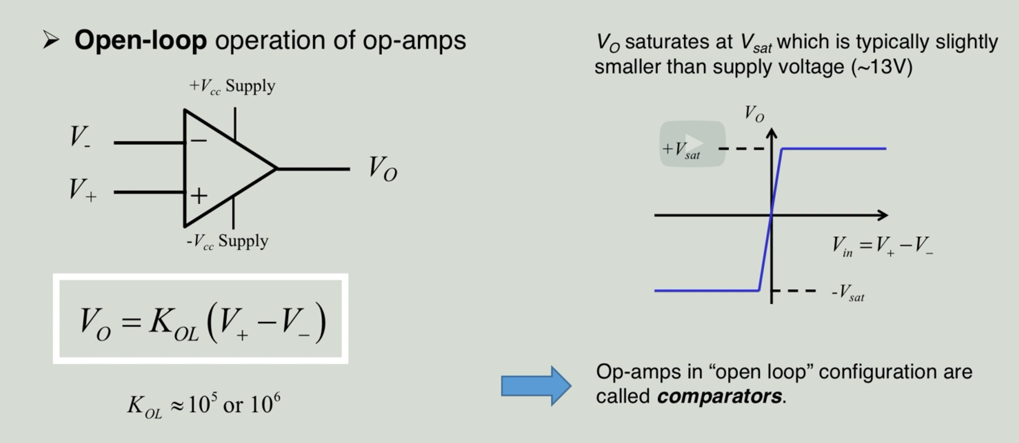
The output voltage (Vo) is the difference between non-inverting (V+) and inverting input (V-). This is then multiplied by a scalar value (amount of amplification) — (Kol). The K value is usually around 10k or 100k.
The output is called saturation voltage (difference between V+ and V-). If you look at the image on the right you see even with small positive or negative input values saturation of voltage is reached quickly. An open loop operation is called a voltage comparator. The downside is the op-amp gain changes with the difference in voltage supply and temperature of the device making it.
Non-inverting (closed) loop operation
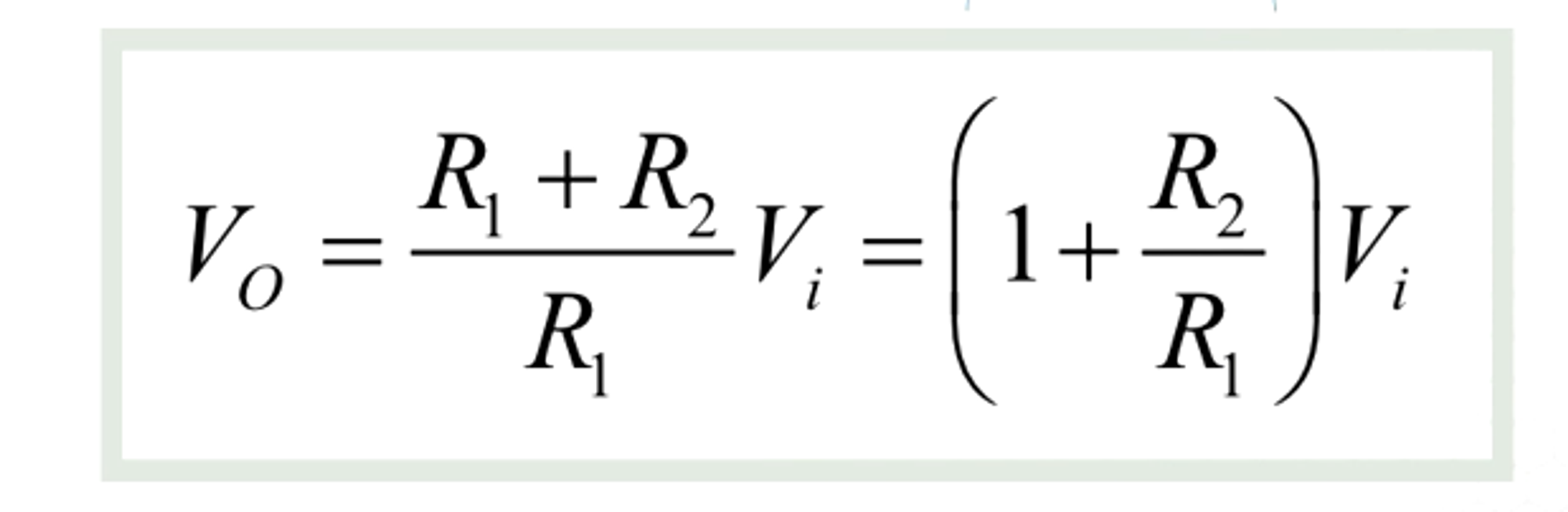
To have a stable gain we use non-inverting op-amps. They use feedback to drive the op-amp. The output voltage is dependent on the input voltage and R1 and R2 (representing the amplifier gain). For specific values, you can use a potentiometer.
Inverting Op-amp
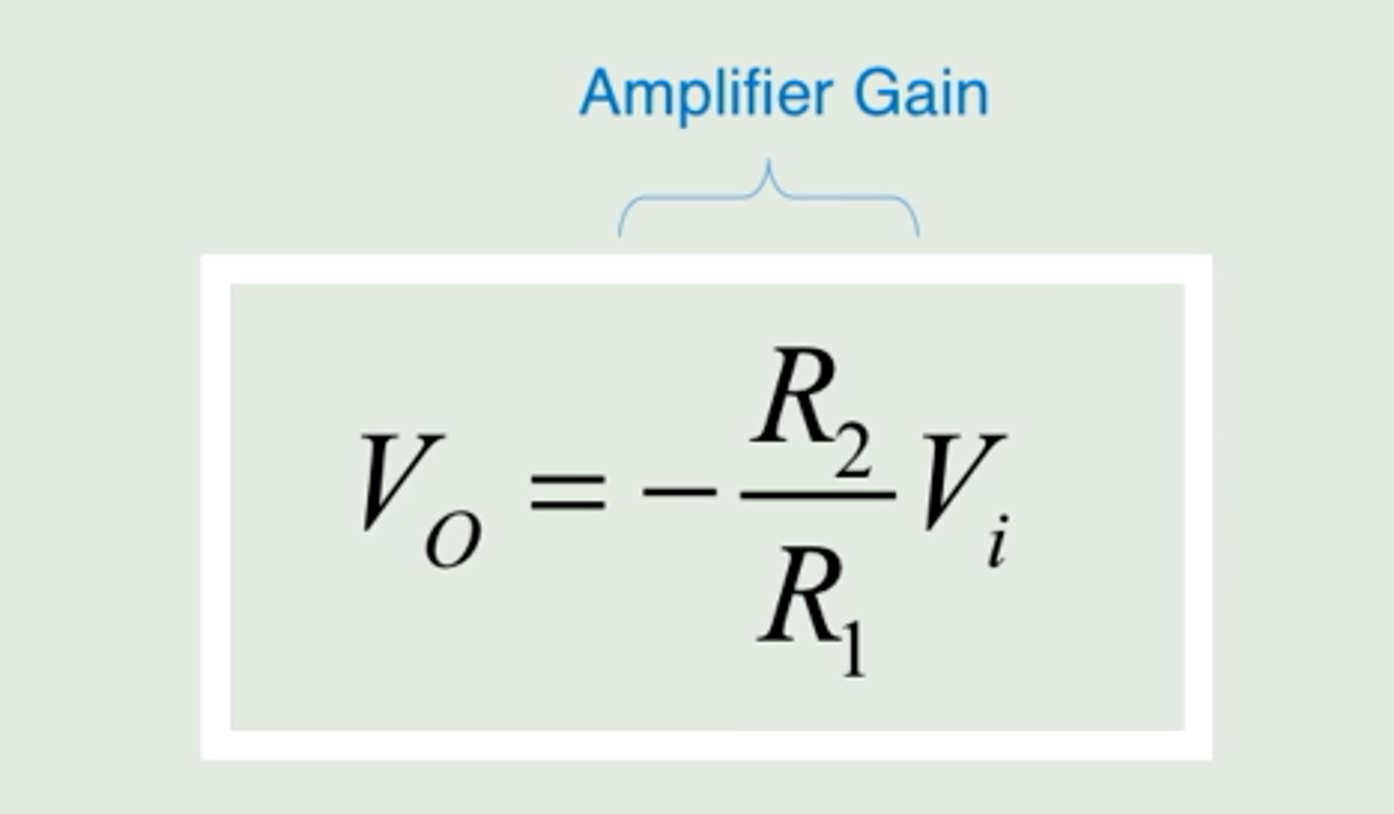
Used to amplify voltage signal and invert it. Gain is determined by R1 and R2. Used in current to voltage converts to current output from the sensor to a voltage output, which is read by analog to digital converter.
Grounding
In a mechatronic device, you have lots of components that are connected. You need all of them to have the same ground point (final destination in the circuit) to make sure you don’t have a difference in electrical potential which can increase the noise and bias (problems that affect the accuracy of sensor data).
Semi-Conductors
Semiconductors are between conductors (they move energy) and insulators (keep out energy). They have a non-linear voltage-current response.
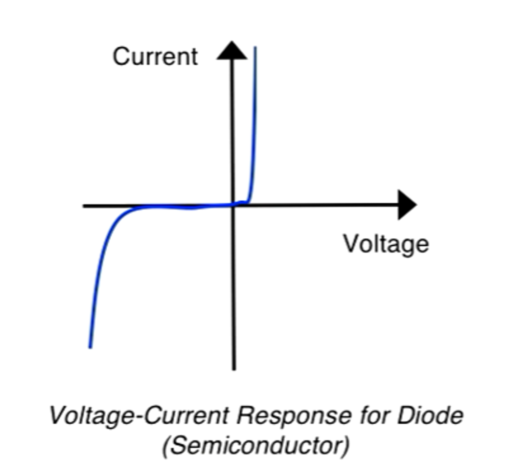
A diode is a type of semiconductor. They allow current to flow in one way. Your applications are lights (LEDs), sensors (photodiodes), and circuit protection devices (flyback diodes).
Ideally, diodes have no resistance, real ones have small resistance. There are 2 modes of operation — forward and reverse-biasing. The difference is the direction of where you want your current to go. In forward bias operations, it is about letting current through. In reverse, it is about eliminating current flow in a certain direction.
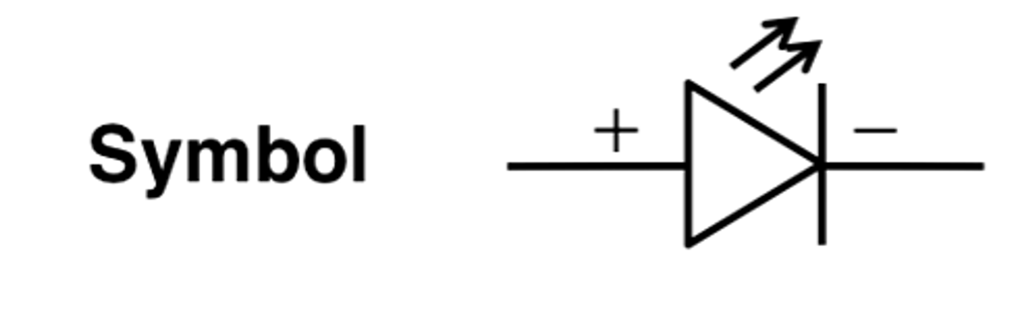
Symbol for diode
Light Emitting Diode (LED) — Emit light when forward bias. Colour is determined by either a semiconductor material or plastic housing over a diode.
Photodiodes (opposite of LEDs) - allow current to pass through when light shines on them. The amount of current passed by the diode is proportional to the amount of light it receives. Ex. Night light.
Flyback diode — Used with DC motors (ones that convert direct current into electrical energy) to make sure your switching elements are not damaged in your circuitry. Side note: Mechatronic devices often used transistors instead of switches.
Bipolar Junction Transistors (BJT)
BJT is a common circuit element, used as a solid state switch. Below is a BJT symbol in a circuit and the different relationships of voltage.
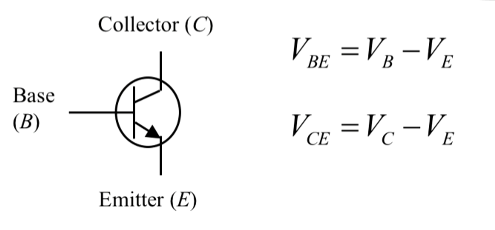
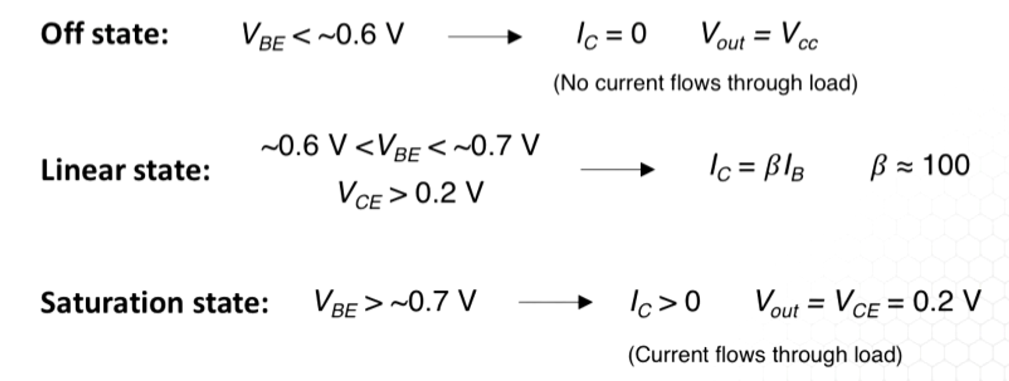
BJT is a current controlled device. The current supplied at Base (B) determines the current flow to C and E. Small base current allows a much larger current to flow from collector to emitters. There are 3 states: off, linear, and saturation state, determined by voltages at C, B, and E.
Only off and saturation states are used in mechatronic devices. As a general rule voltage at the emitter is always lower than the voltage of the base by about 0.6 volts.
In high-current applications like motors and LEDs. They will be switched on using a microcontroller. The microcontroller provides and accepts low currents, meaning they will not be able to power motors and LEDs. MCUs will instead act as a switching element, that will switch the current path between a voltage source and a motor.
Transistor switch circuits are used to switch high power loads from low-power devices. Below is what the integration of a transistor switch circuit looks like.
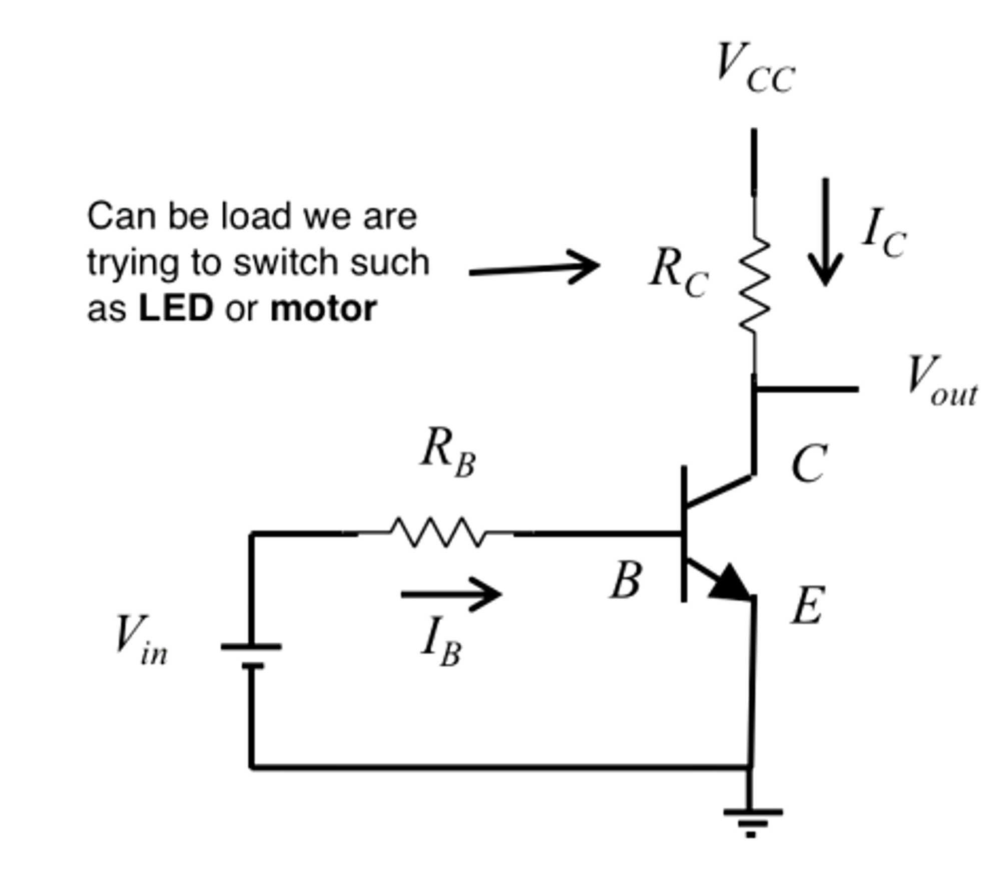
The way this works is Voltage input or V(in) coming from your microcontroller provides energy to the base (B), activating a transistor. Your other voltage source V(cc) moves the current I(c) through the collector, emitter, and eventually grounding point (found at the bottom of E or the emitter— the 3 lines).
Essentially your microcontroller controls the function, but you are using a new voltage source to power higher current devices. There are 2 major states for mechatronic devices: off state and saturation state.
In the off state, the voltage of V(be) or Voltage of the base and emitter is under 0.6V. This means that I(c) = 0 and V(out)= V(cc). This means that no current went through our load.
In a saturation state where V(be) is over 0.7 volts. This means our I(c) is over 0 and V(out) = V(ce) = 0.2V meaning that current did flow through the load.
Designing a Transistor Switch Circuit
Question: When V(i) = 0 (off state) no current flow through the collect and emitter. What voltage of V(i) is required to switch the transistor from off state to saturation state allowing current to flow through load using the circuit below?
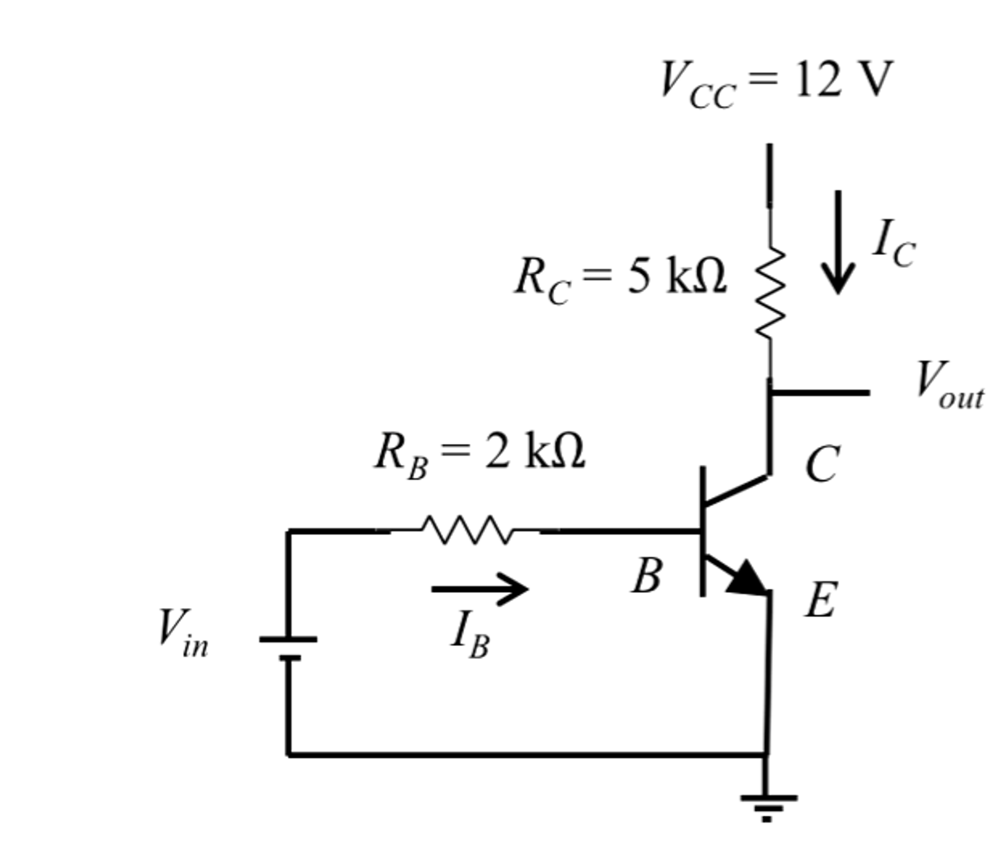
There are 5 known variables and 3 unknown variables
Known:
V(cc) = 12V — R(c) = 5k Ω — R(b) = 2k Ω
$Vout = Vce = 0.2V$ — value in saturation state
Unknown:
V_i = ? I_C = ? I_B = ?
We need to find voltage using Kirchoff’s current law
I_c = (Vcc -Vce)/R_C
I_c = (12-0.2)/5000
I_c = (12-0.2)/5000
I_c = 0.00236A
We then use the linear state equation (before we get to saturation)
I_b =B/I_c
I_b = 0.00236A/100
I_b = 0.00236A/100
I_b = 0.0000236A
V_i = I_BR_B + Vbe
V_i = 0.0000236A * 2000Ω + 0.7V
V_i = 0.747V
To switch on the load you need more than 0.747V.
BJTs are used to build open collector outputs. This allows you to connect sensors to digital input pins on your microcontroller, allowing sensors with different output ranges to create digital high (3.3V or 5V) or digital low (0V).
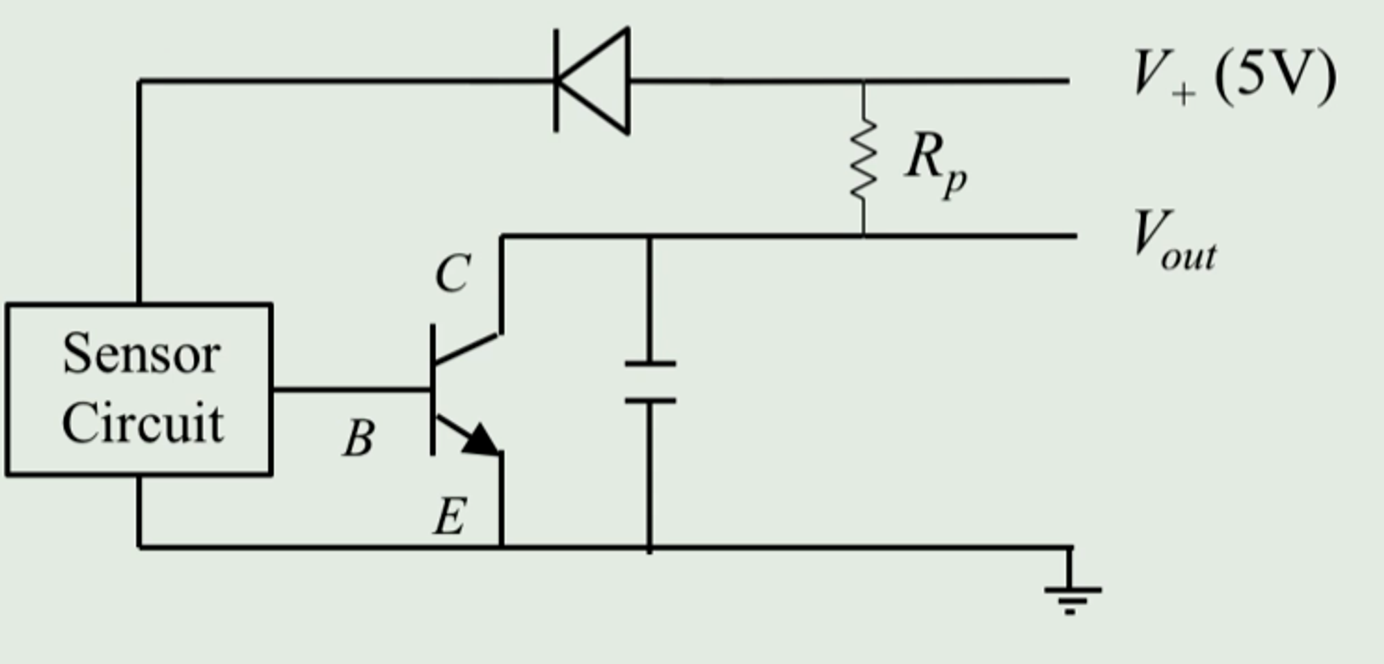
The circuit above is an open collector circuit that uses a sensor to drive the output of the BJT. The pull-up resistor R(p) helps keep the same voltage level for V+ (saturation of positive) and V(out). V+ is the digital (or logic) high voltage (3.3V or 5V).
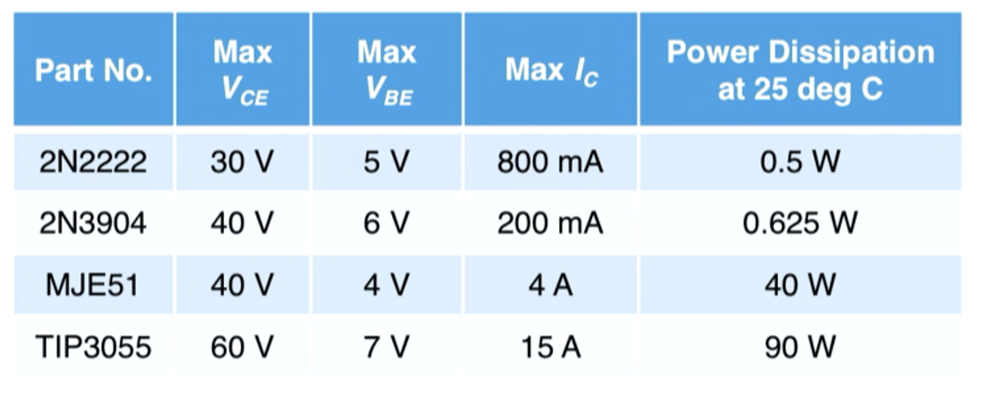
Digital low means that there is not enough to put our BJT in the off state. This means that no current is gonna flow from the collector to the emitters and V(out) will be 5 volts, no current will flow through the pull-up resistor. When you have a digital high for the sensor V(out) will decrease as the collector had current flow through the emitters hitting the grounding point. Below is a set of different BJTs and their specifications.
MOSFET Transistors
The transistor is the interface between high-power and low-power devices in a circuit. MOSFET or Metal-Oxide Semiconductor Field Effect Transistors are a common type of transistor used for switching. MOSFET is used for high-power applications (ex. Motors) and BJTs are used for low-power applications (ex. sensors). The voltage supplied at gate G determines the flow between D (drain) to S (source).
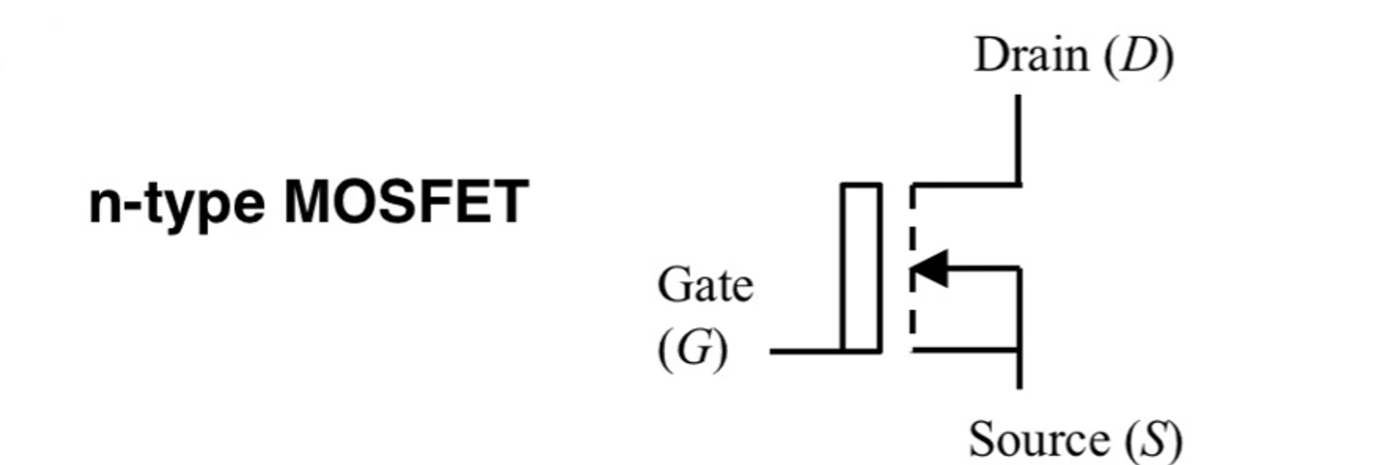
They have 2 states: Off, and Saturation (on). In off state: Drain source resistance is high —> no current flows from Drain to Source. Saturation (On) State: Drain-source resistance is low (below 1 ohm) and current flows from D to S. Internal resistance is high at the MOSFET gate (10^14 ohms) meaning no current flows through the gate. This is what allows you to separate your high-power and low-power applications. Important specifications for MOSFET transistors:
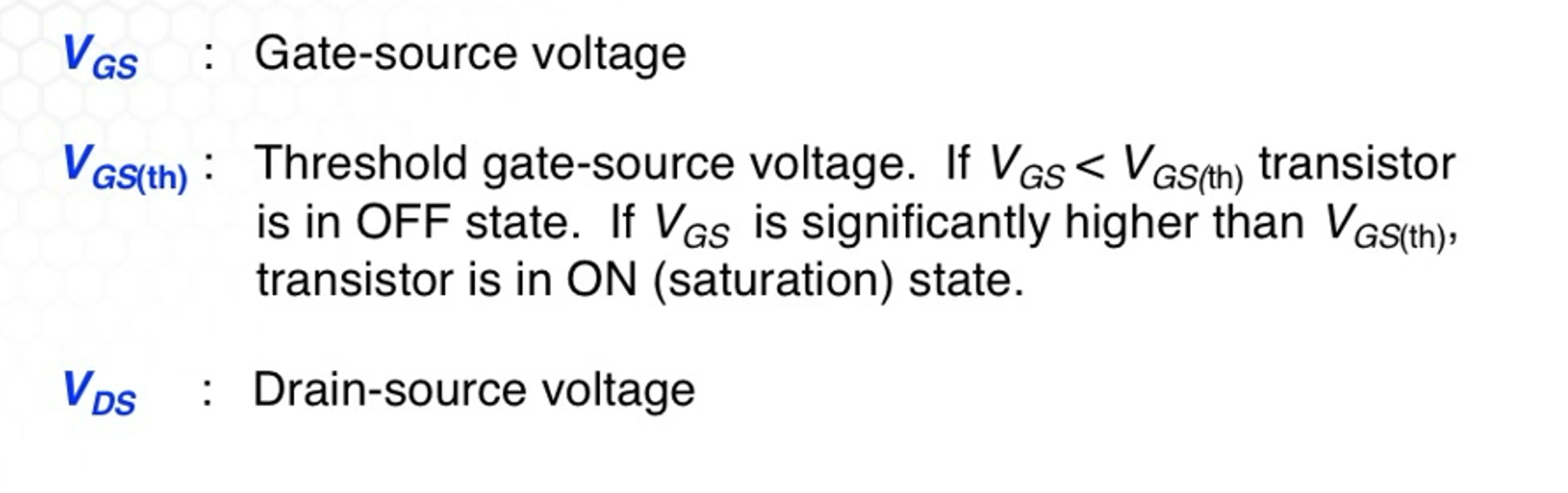
The switching speed is in the nanosecond range. Commonly used to switch high-power loads (motors, LEDs) from logic level devices such as microcontrollers.
Motor Circuits
DC motors rely on electromagnetics to convert current flow to physical motion. Since MCUs can not power high loads you use motor driver circuits. With common motor circuits, you are limited by binary operations of on and off and you can only choose one direction of operation and the speed is the same and can not be changed.
To be able to change directions we use an H-Bridge. They get their name from the shape they resemble (H). Below is a schematic of an H-bridge.
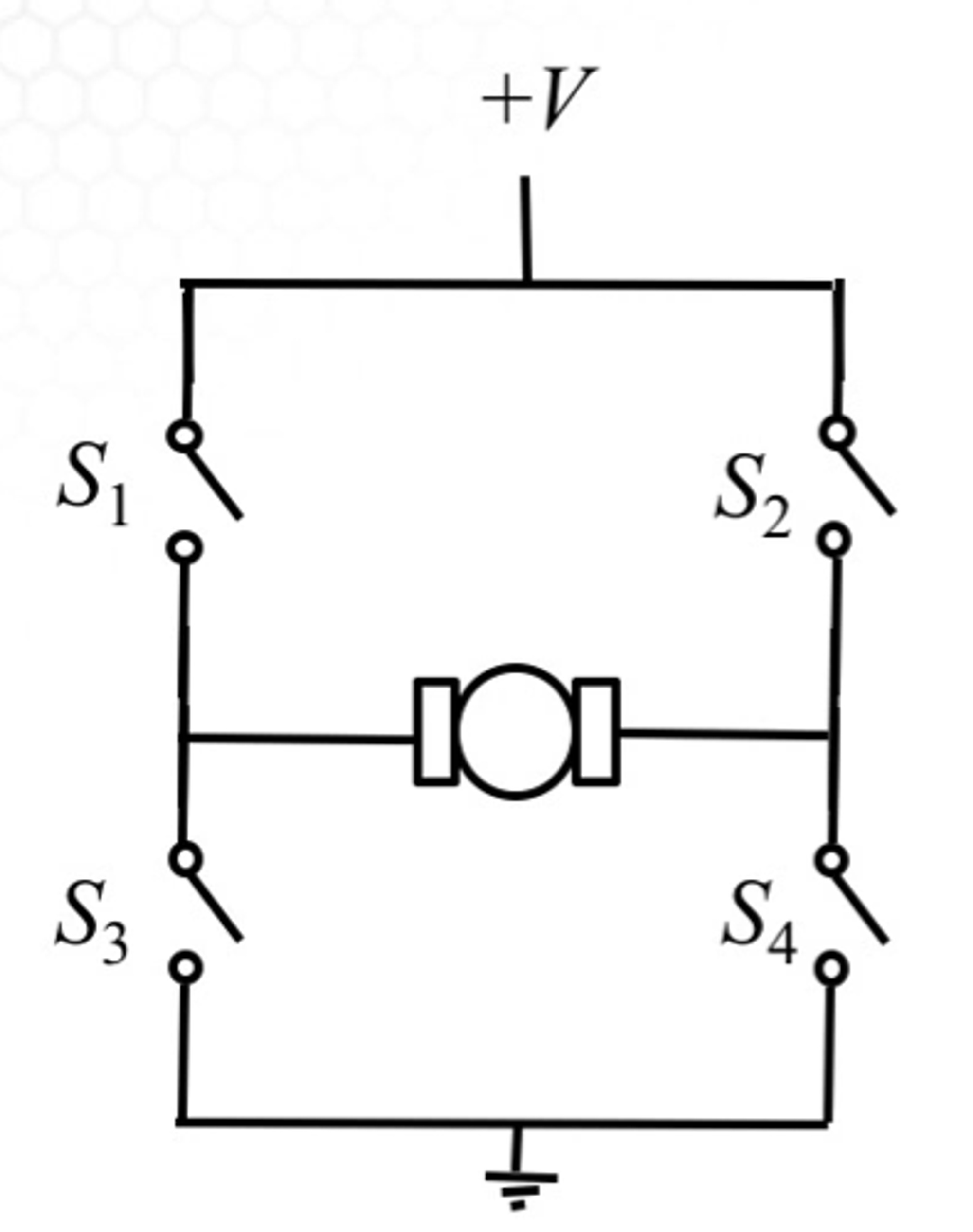
When switches s1 and s4 are open then s2 and s3 are closed and the motor turns in one direction. When switches s1 and s4 are closed and s2 and s3 are open then the motor turns in the other direction.
H-bridges are not built from mechanical switches, they are built with transistors, diodes, and logic gates with transistors acting as the switching elements. These devices have fast switching times (nanosecond range) and may have built-in flyback diodes.
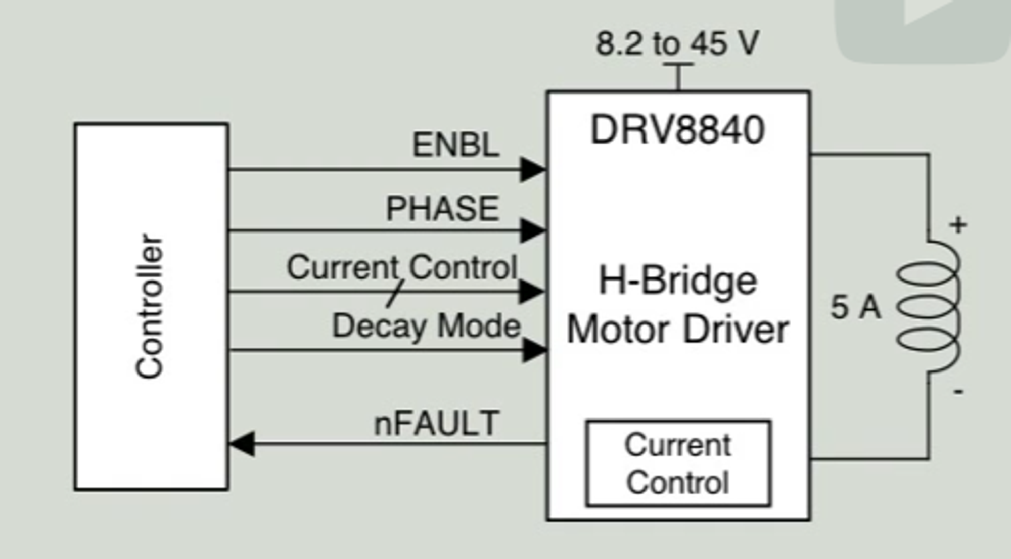
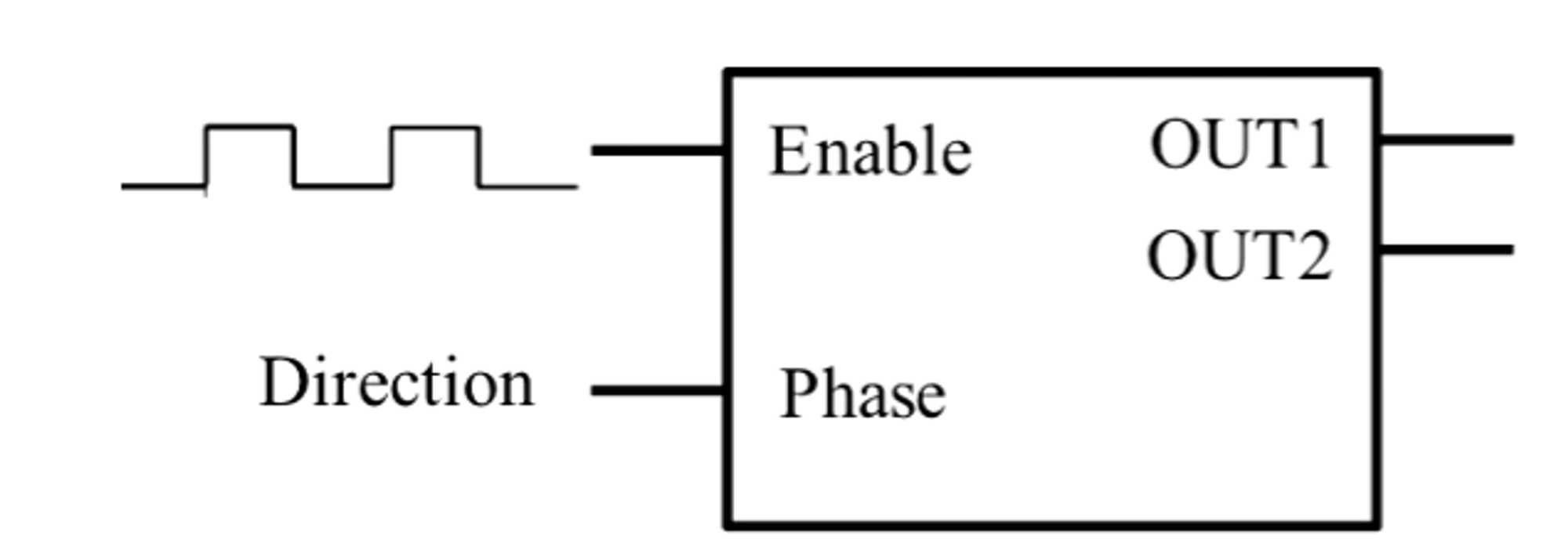
Above is an example of integrated circuits with an H-bridge to be used for direct current motors. The Enable (ENBL) line connected to MCU is used to switch the motor on and off. Phase is used to set the direction of the motor. Other lines are used for more advanced functionality.
With H-bridge, we can just have our motor go in 1 direction or another. To change the speed of our motor we use a digital-to-analog converter (DAC). DAC circuits generate a variable output given a binary number input. Below is a schematic.
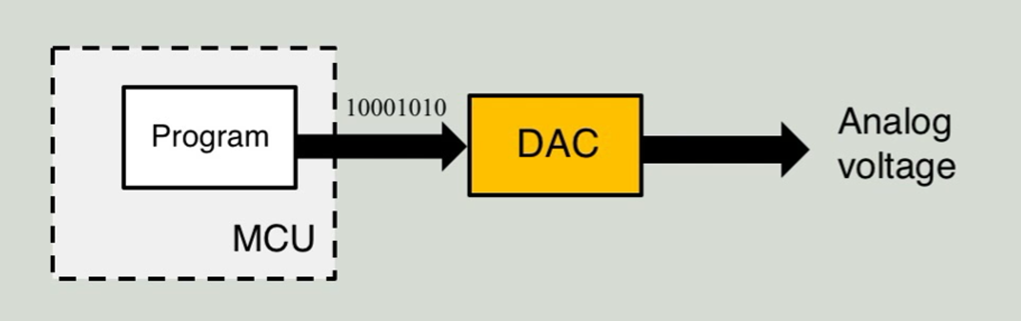
You usually need 8 bits (or binary inputs). For each bit, we need an MCU output pin, which is not an efficient use of wires.
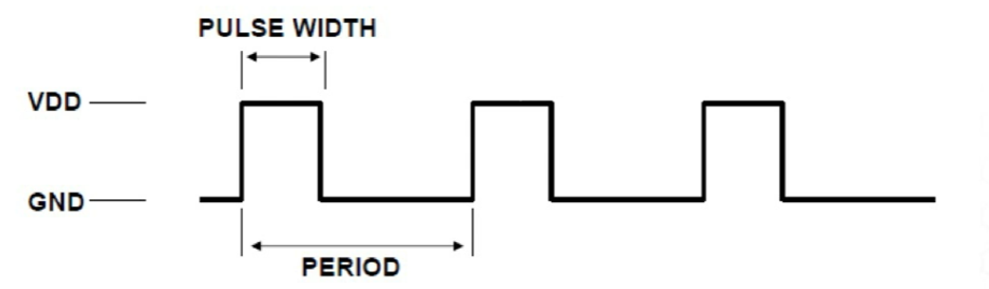
Instead, we can use pulse width modulation (PWM) which uses a single GPIO pin to create a variable voltage output. There are 3 quantities that define a PWM signal: Pulse width, period, and voltage. Below is an example of a PWM wave.
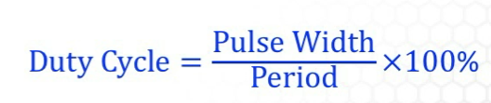
To compute our voltage or duty cycle we can use the following formula.
Below are 3 examples of a duty cycle of PWM signals. All of the PWM signals have a fixed frequency that is independent of the duty cycle. All these signals have a frequency of 1/100ms = 10Hz.
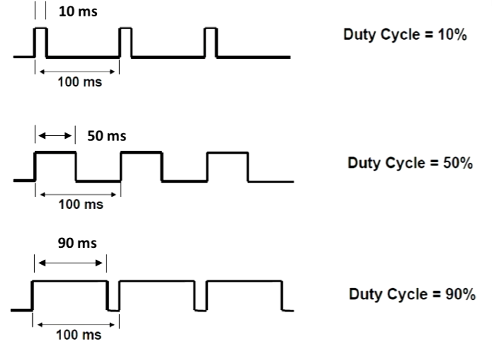
To get the average voltage we use the following formula.

We can change the average voltage by changing the duty cycle. For example, If V(dd) was 12V that we can produce an average voltage in the range of 0-12V range adjusting the duty cycle between 0-100%.
As a variable power signal, the PWM signal draws current I at some voltage. To find out the average power per cycle we use the following formula.
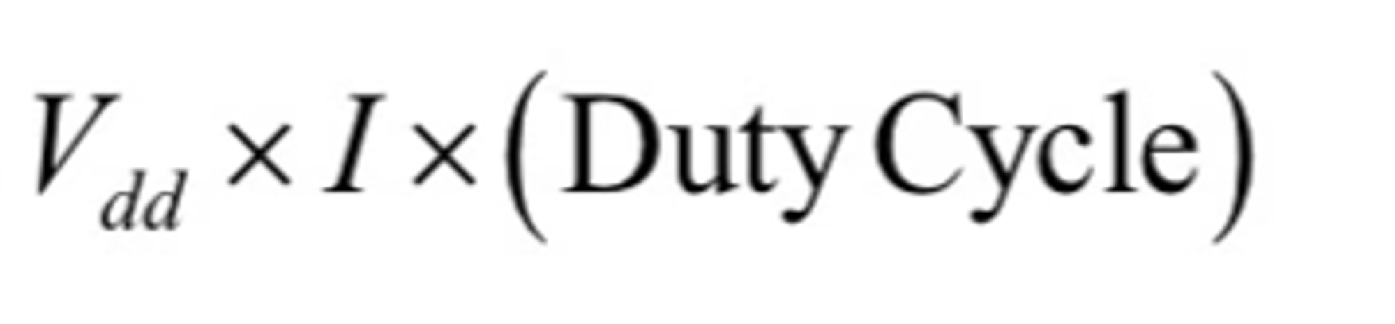
This means that we can change the amount of power or by changing the duty cycle. PWM signal is input into the enable pin of an H-bridge, which turns the H-bridge on and off. If we send a PWM signal to the enable pin H-bridge, then it will turn it on and off and turn outputs at the same rate as our PWM signal. We will then need another digital input signal from a GPIO pin and we can put that into the phase or direction input of our H-Bridge. All it does is when the motor is 0 it will turn in one direction, if it is 1 it will turn in the other direction. Below is a schematic for pin inputs of motors.
To be able to measure the speed and position of the rotating motor we use encoders are sensors that connect rotating devices to measure angular speed or position.